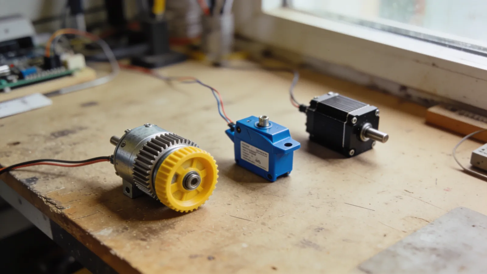
Choosing a motor is the decision that comes up most often in robotics projects. The first motor you buy usually turns out to be either too fast and underpowered, or too slow and unnecessarily powerful. The reason is simple: it’s rarely explained how to translate the numbers in motor catalogs into practical project specifications.
In this article, I compare three types of motors in terms of real-world usage, demonstrate torque calculations with specific numbers, and explain what to look for when selecting a driver board.
Three motor types, three different tasks
| DC with gearhead | Servo | Stepper | |
|---|---|---|---|
| Motion | Continuous rotation | Specific angle (0–180°) | Step-by-step, full rotation |
| Position data | None (encoder required) | Internal | By step count |
| Torque/weight | Good | Medium | Low |
| Current consumption | Varies by load | Varies depending on the load | High even when idle |
| Difficulty in control | Easy (PWM) | Very easy | Moderate (driver required) |
| Typical use | Wheel, track | Arm, steering, gimbal | 3D printer, CNC |
DC gearmotors
The backbone of robotics competitions. It consists of a DC motor and a gearbox mounted in front of it. The gearbox reduces speed and increases torque—which is exactly what you need in robots.
Understanding the reduction ratio
A 1:50 ratio means that when the motor shaft rotates 50 times, the output shaft rotates once. This change affects two things in opposite ways:
- The speed drops by a factor of 50. A 10,000 rpm motor → 200 rpm output.
- Torque increases approximately 50-fold (in practice, about 70–80% due to gear efficiency).
In other words, choosing a reduction ratio is directly a decision between “speed or power”:
| Ratio | Typical RPM | Character | Suitable Application |
|---|---|---|---|
| 1:10 | 1,000+ rpm | Very fast, weak | Fan, propeller |
| 1:30 | ~800 rpm | Fast | Fast line-following |
| 1:50 | ~400 rpm | Balanced | General-purpose robot |
| 1:100 | ~200 rpm | Powerful, slow | Mini sumo, pushing |
| 1:300 | ~60 rpm | Very powerful | Robot arm, lifting |
Torque calculation
The rough answer to the question “How much torque is required?” is found using the following formula:
Gerekli tork (kg·cm) =
   (Toplam ağırlık × Tekerlek yarıçapı × Güvenlik katsayısı) / Motor sayısı
Example: A two-motor robot weighing 1.2 kg with wheels having a radius of 3.5 cm. On a flat surface, the safety factor is 1.5:
(1,2 × 3,5 × 1,5) / 2 = 3,15 kg·cm → motor başına ~3,2 kg·cmIf the robot needs to climb a ramp or push an opponent, increase the safety factor to 3. For push-focused robots like mini sumo, 5–8 kg·cm per motor is typical.
The torque value listed in the catalog is typically the stall torque—that is, the value at the moment the motor is completely locked. Running the motor continuously at this point will burn out the windings. For continuous operating torque, account for 30% of the stall torque.
Encoder: Allowing the robot to track its own movement
In simple projects, “move forward for two seconds” is sufficient. However, as the battery weakens, the same command covers a shorter distance. An encoder eliminates this uncertainty.
The most common type in robotics is the quadrature magnetic encoder: it consists of a magnet mounted on the motor shaft and two Hall sensors, providing both the number of revolutions and the direction of rotation.
volatile long sayac = 0;

void encoderKesme() {
  if (digitalRead(ENC_B)) sayac++;
  else                    sayac--;
}

void setup() {
  attachInterrupt(digitalPinToInterrupt(ENC_A), encoderKesme, RISING);
}

// Mesafe hesabı
float mesafeCm() {
  const float TUR_BASINA_TIK = 1400.0;      // motor + redüktör + encoder
  const float TEKERLEK_CEVRE = 2 * 3.14159 * 3.5;
  return (sayac / TUR_BASINA_TIK) * TEKERLEK_CEVRE;
}
You can add PID speed control along with the encoder; this way, the robot travels at the same speed on both ramps and flat surfaces.
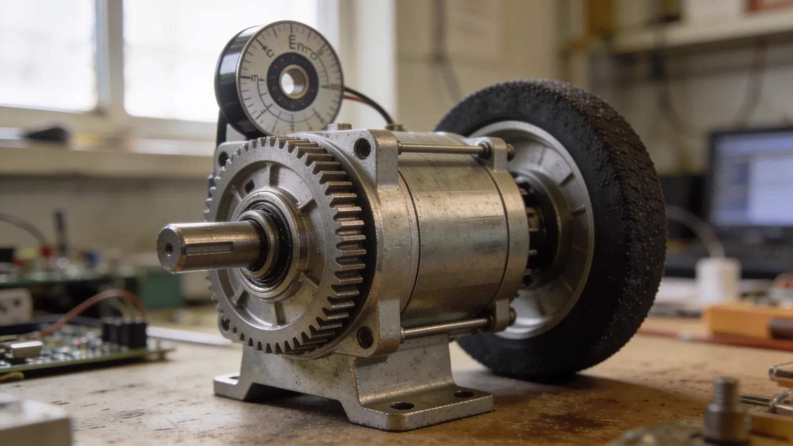
Servo Motors
A servo motor is essentially a package: DC motor + gearbox + position sensor + control circuit. You specify an angle, and the servo moves to that position and stops there.
The difference between analog and digital servos
- Analog servo: Performs position adjustments at ~50 Hz. Inexpensive, slow response, low holding force. The SG90 falls into this category.
- Digital servo: Performs adjustments at over 300 Hz. Faster, stronger holding power, draws more current.
If you’re experiencing vibration or sagging in a robotic arm or steering mechanism, the solution is usually to switch to a digital servo.
Continuous-rotation servo
Servos with position feedback disabled are called “continuous rotation” servos. You control speed instead of angle. It’s practical, but it has two drawbacks: speed control is coarse, and there’s no position feedback. A geared DC motor is generally a better choice for wheel drive.
Never power servo motors from the Arduino’s 5V pin. Even the SG90 can exceed 500 mA during movement; two servos will reset the board. Use a separate 5V regulator and share the GNDs.
Stepper Motors
A stepper motor rotates the shaft in fixed-angle steps (typically 1.8° per step, or 200 steps per revolution). You know the position without a sensor—the shaft has rotated exactly as many steps as the driver sent.
Why they are not preferred for robot wheels
- Heavy: They are significantly heavier than DC motors for the same torque.
- Continuous current: The coils are powered even when the motor is at rest; battery life drains rapidly.
- Torque drops at high speeds: It weakens as speed increases.
- Step skipping: If overloaded, it skips steps, and position information silently becomes corrupted.
In contrast, stepper motors are the right choice for 3D printers, CNC machines, camera slides, and any application requiring precise positioning.
Microstepping
Drivers such as the A4988 or DRV8825 divide a single step into 2, 4, 8, 16, or even 32 parts. This both quietens and smooths the motion. However, microstepping does not increase precision; it merely provides smoothness. Holding torque decreases during microstepping.
Selecting a Motor Driver Board
You cannot connect the motor directly to the microcontroller; a driver must be in between. And driver selection is just as important as motor selection.
| Driver | Current (continuous) | Voltage Drop | Evaluation |
|---|---|---|---|
| L298N | ~2 A | 1.4–2 V | Old, inefficient, runs very hot |
| L293D | 0.6 A | ~1.8 V | Only for very small motors |
| TB6612FNG | 1.2 A (peak 3 A) | ~0.1 V | The best balance for small robots |
| DRV8833 | 1.5 A | ~0.1 V | Inexpensive, efficient, compact |
| VNH2SP30 | 14 A | Very low | Powerful robots, sumo |
| BTS7960 | 43 A | Very low | Large robots, extreme power |
The L298N is still the best-selling driver, but its technology dates back to the 1990s. The MOSFET-based TB6612FNG delivers up to 25% more voltage to your motor from the same battery. This means your robot will be faster without having to make any changes.
PWM frequency
If your motor emits a high-pitched hum while running, the PWM frequency is within the audible range. Arduino’s default frequency of 490 Hz is exactly what causes this problem.
Raising the frequency above 20 kHz completely eliminates the noise. On the ESP32, this is a one-line configuration; on the Arduino, you’ll need to adjust the timer registers.
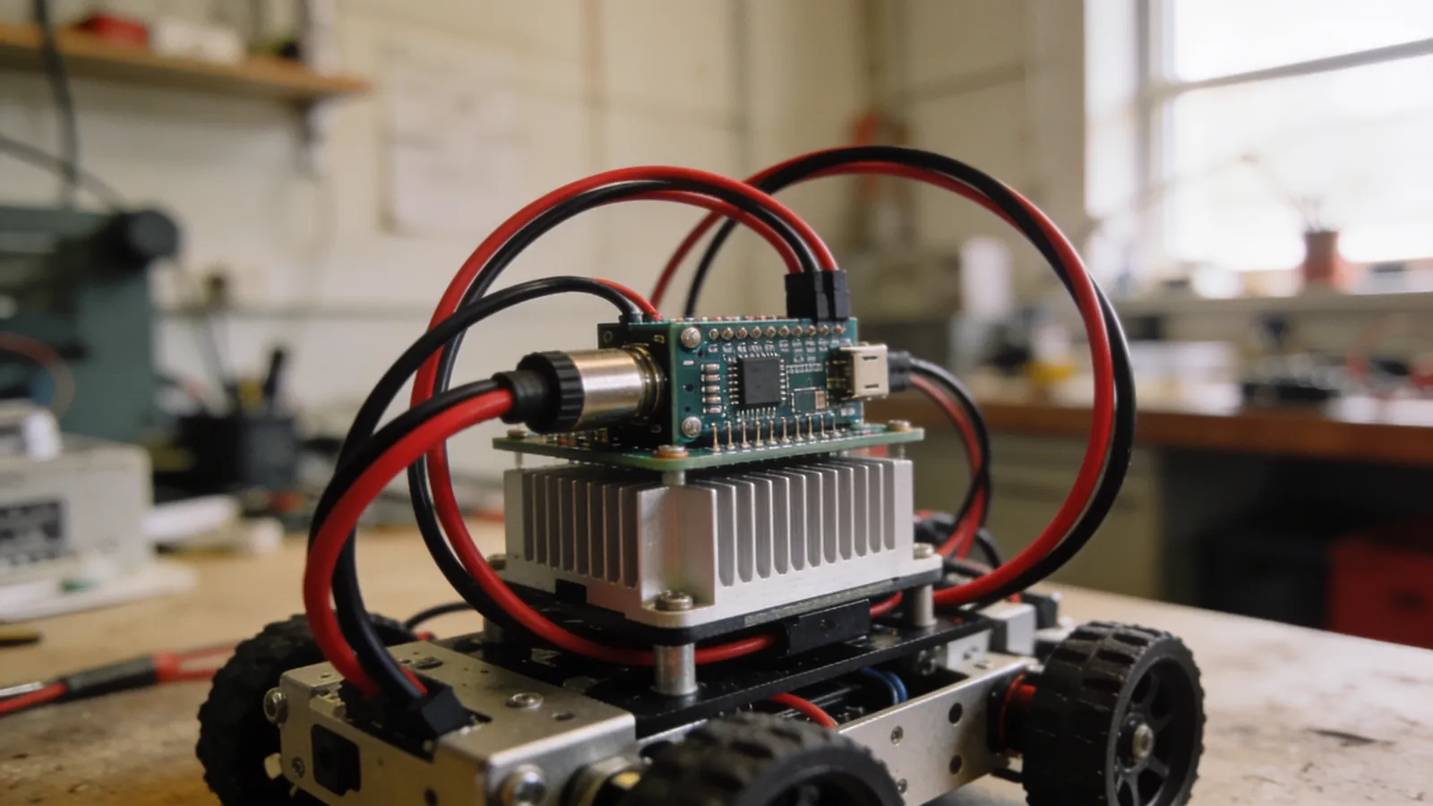
Heat, Efficiency, and Motor Lifespan
After selecting a motor, most teams completely forget about it. However, how the motor is operated directly determines how long it will last.
Why Do Motors Overheat?
The current drawn by a DC motor is directly proportional to the torque it produces. As the motor is under greater load, it draws more current; more current means more heat. Heat degrades the insulation of the windings, and at some point, the windings short-circuit.
The critical moment is when the motor isn’t rotating but voltage is applied—this is called a stall. At this point, the motor draws maximum current and produces no work; all the energy is converted into heat. The motors of a sumo robot pressing against an opponent are in exactly this state.
Practical Precautions
- Set a current limit. If your driver board can read the current, reduce the PWM when the threshold is exceeded.
- Do not operate the motor at continuous stall torque. If the robot cannot move forward, have it retreat for a few seconds and then attack again.
- Check the motor housing by hand. If it’s too hot to touch, you’re at the limit.
- Do not exceed the rated voltage. A 20% overshoot is acceptable; double that will burn out the windings.
Soft Start
Ramping the PWM from zero to 255 instantly causes both current spikes and gear wear. A ramp of a few hundred milliseconds protects both the motor and the driver:
int hedefHiz = 255, mevcutHiz = 0;
const int ADIM = 8;                      // her döngüde artış

void hizGuncelle() {
  if (mevcutHiz < hedefHiz) mevcutHiz = min(mevcutHiz + ADIM, hedefHiz);
  else if (mevcutHiz > hedefHiz) mevcutHiz = max(mevcutHiz - ADIM, hedefHiz);
  analogWrite(MOTOR_PWM, mevcutHiz);
}
Caution: A soft start extends the response time. In categories where sudden acceleration is critical—such as Mini Sumo—keep the ramp very short or omit it entirely.
Transmission Options
The connection between the motor shaft and the wheel is also a design decision and is often taken for granted.
| Method | Pros | Cons |
|---|---|---|
| Direct Drive | Simple, efficient, lossless | The motor position determines the wheel |
| Belt-pulley | The motor is freely positioned, quiet | Belt tension requires adjustment; the belt may slip |
| Gear transmission | Additional reduction, powerful | Backlash, noise, alignment |
| Chain | Transfers high torque | Heavy; unnecessary in small robots |
Direct drive is almost always the right choice for small competition robots: fewest parts, least loss, fewest points of failure. A belt-and-pulley system only makes sense if you need to place the motor in a different location within the chassis.
Shaft connection
How you secure the wheel to the shaft is also important. Connections made solely by a tight fit will rotate on the shaft under high torque, causing the robot to lose power. The most robust solution is a D-shaped flattened shaft with a hub that fits onto it; the second-best option is to secure it with a set screw.
Common Mistakes
- Basing calculations on RPM instead of torque. Ask “How many kg·cm?” instead of “How many RPM?”
- Mistaking stopping torque for continuous torque. Calculate using 30% of the catalog value.
- Selecting a motor that’s too small. The motor’s starting current is 5–8 times the continuous current.
- Exceeding the motor’s rated voltage. Applying 12 V to a 6 V nominal motor provides a quick start in the short term but will wear out the brushes and windings in the medium term.
- Forgetting the common ground. The driver board’s GND must be connected to the microcontroller’s GND.
- Failing to filter motor noise. Soldering a 100 nF capacitor to the terminals of brushed DC motors resolves unexplained spikes in sensor readings.
Summary Decision Table
Match your project with these three questions:
- Does it need to rotate continuously and require power? → Geared DC motor + MOSFET driver.
- Does it need to stop at a specific angle? → Servo motor (digital servo if the load is heavy).
- Do you need precise and repeatable positioning? → Stepper motor + microstep driver.
The next step after selecting a motor is to set up the power system correctly. The current drawn by the motors directly determines the choice of battery; I covered this topic in the LiPo battery guide along with the C-rate and current calculations.
Frequently asked questions
Robotum için ne kadar tork gerekli?
Basit hesap: Tork = (Toplam ağırlık × Tekerlek yarıçapı × İvme katsayısı) / Motor sayısı. 1 kg ağırlık, 3 cm yarıçaplı tekerlek ve 2 motor için motor başına yaklaşık 1,5–2 kg·cm yeterlidir. Rampa veya itiş gerekiyorsa bu değeri iki katına çıkarın.
Servo motor mu DC motor mu kullanmalıyım?
Sürekli dönmesi gereken yerlerde (tekerlek, fan, konveyör) redüktörlü DC motor; belirli bir açıya gidip orada durması gereken yerlerde (robot kolu, direksiyon, kamera açısı) servo motor kullanın.
Step motor robotlarda kullanılır mı?
Kullanılır ama tekerlek tahrikinde nadiren. Step motor konum hassasiyeti sunar, buna karşılık ağırdır, çok akım çeker ve yüksek devirde tork kaybeder. 3B yazıcı, CNC ve hassas konumlandırma gerektiren eksenlerde doğru tercihtir.
L298N sürücü neden ısınıyor ve güç kaybettiriyor?
L298N eski bir bipolar transistör teknolojisi kullanır ve motor başına yaklaşık 1,4–2 V gerilim düşümü yaratır. 7,4 V pilden motora sadece ~5,5 V gider, kalan enerji ısıya dönüşür. Yerine MOSFET tabanlı TB6612FNG veya DRV8833 kullanın.
Encoder gerekli mi?
Robotun ne kadar yol gittiğini bilmesi gerekiyorsa evet. Encoder olmadan “iki saniye ileri git” komutu pil doluyken ve azken farklı mesafeler üretir. Çizgi izleyen gibi dış referansı olan robotlarda encoder şart değildir.
Comments
0No comments yet. Be the first to comment!