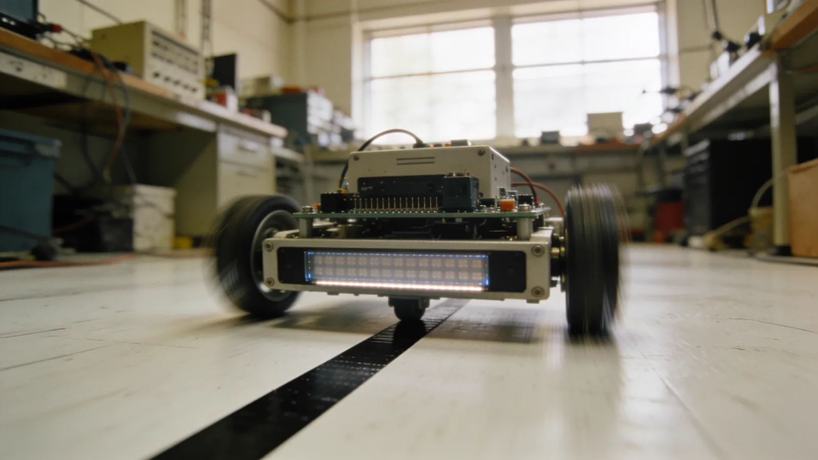
A line-following robot is the most effective project for learning robotics. Here’s why: through a single task, you learn sensor readings, noise filtering, control theory, and motor control all at the same time. The basic version can be up and running in an afternoon; taking it to competition level, however, takes months.
In this guide, I’ll walk you through building a line-following robot in two phases. First, we’ll get a working robot up and running; then we’ll tackle the elements that make it faster—namely, sensor array design, calibration, and PID tuning—one by one.
How it works: what the robot is actually measuring
A line-following robot has one job: to constantly measure where the line is relative to the robot’s center and try to reduce that difference to zero. We call this difference the error.
If the robot is directly on top of the line, the error is zero. If the line shifts to the right, the error is positive; if it shifts to the left, the error is negative. The motors’ job is to correct this error. The entire control algorithm revolves around this single number.
How Does an Infrared Reflective Sensor Work?
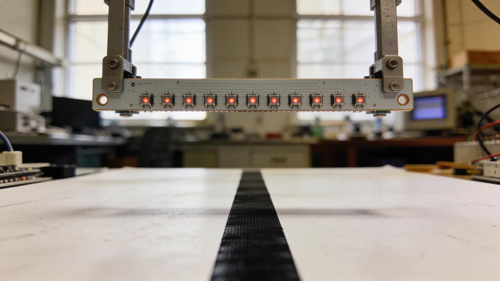
The sensors we use (QRE1113, TCRT5000, and QTR series) consist of an infrared LED and a phototransistor. The LED emits light toward the floor, and the phototransistor measures the reflected light:
- A white surface reflects a lot of light → the sensor reads a low resistance.
- A black line absorbs the light → the sensor reads a high resistance.
This difference is the signal on which the entire system relies. The greater the difference, the more stable the robot becomes—which is why the track material and sensor height are just as important as the code.
Sensor Array Design
The sensor array is the robot’s eye. Three decisions here directly determine its performance.
1. Number of sensors
| Number of sensors | Resolution | Suitable Applications |
|---|---|---|
| 3 | Very coarse | For educational purposes only; slow robot |
| 5 | Acceptable | First robot, medium speed |
| 8 | Good | Competition entry level |
| 12–16 | High | High speed, sharp turns |
Increasing the number of sensors not only improves accuracy but also increases the angle at which the robot can detect the line without losing it. With 5 sensors, the line may completely go off the track during a sharp 90-degree turn; with 12 sensors, it won’t.
2. Distance Between Sensors
General rule: The distance between sensors should be half the width of the line. If the standard competition line is 19 mm, a sensor spacing of 8–10 mm is ideal. This ensures that the line always affects at least two sensors simultaneously, allowing you to calculate intermediate positions.
3. Distance from the track to the wheel
This is where most robots go wrong. The farther the sensor array is in front of the wheel axis, the sooner the robot detects the turn—which is good. But if it’s too far forward, the robot’s turn will swing the array too far off the line—which is bad.
A practical range is 4–8 cm. Move it forward for fast robots, and backward for slow robots or tracks with sharp turns.
Calibration: If skipped, nothing will work
Raw sensor values vary by environment. A sensor that reads between 200 and 800 in your workshop might read between 350 and 700 in the competition hall. If you set a fixed threshold, the robot won’t work there.
The solution is to perform calibration at startup: sweep the robot back and forth over the line for a few seconds, and record the smallest and largest values each sensor detects.
void kalibreEt() {
  for (int i = 0; i < SENSOR_SAYISI; i++) {
    minDeger[i] = 1023;
    maxDeger[i] = 0;
  }
  unsigned long baslangic = millis();
  while (millis() - baslangic < 3000) {   // 3 saniye süpür
    sagaSolaSalin();
    for (int i = 0; i < SENSOR_SAYISI; i++) {
      int v = analogRead(sensorPin[i]);
      if (v < minDeger[i]) minDeger[i] = v;
      if (v > maxDeger[i]) maxDeger[i] = v;
    }
  }
  motorDur();
}
Afterward, you normalize each reading to the 0–1000 range:
int normalize(int ham, int i) {
  long d = (long)(ham - minDeger[i]) * 1000 / (maxDeger[i] - minDeger[i]);
  return constrain(d, 0, 1000);
}Repeat the calibration at every competition, and even every lap if the lighting changes. It might seem tempting to save the calibration data to EEPROM for use at the next startup, but if the environment changes, the old data will mislead the robot.
Error calculation: weighted average
The best way to derive a single position value from sensor readings is to use a weighted average. You assign a position weight to each sensor and calculate the average based on the readings.
long konumHesapla() {
  long toplamAgirlik = 0;
  long toplamDeger   = 0;

  for (int i = 0; i < SENSOR_SAYISI; i++) {
    int v = normalize(analogRead(sensorPin[i]), i);
    toplamAgirlik += (long)v * (i * 1000);  // sensörün konum ağırlığı
    toplamDeger   += v;
  }

  if (toplamDeger < 50) return sonKonum;   // çizgi kayboldu
  sonKonum = toplamAgirlik / toplamDeger;
  return sonKonum;
}
In an array of 8 sensors, the center value is 3500. The error is simply:
int hata = konumHesapla() - 3500;To see how this calculation works, drag the line in the module below. Watch how the values read by the sensors are converted into a single position value and what happens when the line exits the array.
sonKonum Important note: When the line disappears completely, the robot continues in the last known direction. This single line saves the robot on tracks with gaps.
PID control: converting the error into motor speed
We have an error; now we need to convert it into motor speed. The three components of PID control handle this from three different angles:
- P (proportional): The larger the error, the larger the correction. The main driving force.
- I (Integral): It sums up small errors that accumulate over time. Generally unnecessary—and even harmful—in line-following.
- D (derivative): It responds to the rate of change of the error. It dampens oscillations and allows the robot to anticipate turns.
int  sonHata = 0;
long integral = 0;

void loop() {
  int hata = konumHesapla() - 3500;

  integral += hata;
  integral = constrain(integral, -10000, 10000);   // integral şişmesini engelle

  int turev = hata - sonHata;
  sonHata   = hata;

  int duzeltme = (Kp * hata) + (Ki * integral) + (Kd * turev);

  int solHiz  = constrain(TABAN_HIZ + duzeltme, 0, 255);
  int sagHiz  = constrain(TABAN_HIZ - duzeltme, 0, 255);

  motorSur(solHiz, sagHiz);
}
Adjusting the Coefficients in Order
PID tuning is a trial-and-error process, but it’s not random. Follow this order:
- Set Ki = 0 and Kd = 0. Keep the base speed low.
- Increase Kp until the robot follows the line. It’s normal for it to zigzag a bit.
- Increase Kp until oscillation begins, then reduce it by 20%.
- Add Kd and increase it until the oscillation dies out. Kd is typically 5–20 times Kp.
- Increase the base speed. If the robot malfunctions, increase Kd a little more.
- Finally, try adjusting Ki with very small values (on the order of 0.0001). If you don’t see any benefit, leave it at zero.
If you’re curious about the mathematics behind PID and the physical meaning of each coefficient, check out my standalone PID control guide.
Change the coefficients one at a time and record the changes in a notebook. If you adjust two coefficients at the same time, you’ll never be able to tell which one made a difference. Being able to make live adjustments via Bluetooth or a potentiometer can cut this process down by hours.
Ways to Increase Speed
Once you have a working robot, the real engineering begins: completing the same track faster.
Variable Base Speed
Instead of a fixed speed, use a speed that slows down as the error increases. Full throttle on straightaways, automatic braking in turns:
int mutlakHata = abs(hata);
int tabanHiz = map(mutlakHata, 0, 3500, MAKS_HIZ, MIN_HIZ);
tabanHiz = constrain(tabanHiz, MIN_HIZ, MAKS_HIZ);
This single change noticeably reduces lap times on most robots.
Motor Braking
Slowing down the inner wheel on a sharp turn may not be enough; you need to make it turn in the opposite direction. If your driver board supports it, allow the speed to be negative:
int solHiz = constrain(tabanHiz + duzeltme, -255, 255);
int sagHiz = constrain(tabanHiz - duzeltme, -255, 255);
Mechanical improvements
- Lower the center of gravity. A tall robot may tip over or lift a wheel when turning.
- Improve tire grip. Silicone tires directly increase cornering speed.
- Reduce weight. As inertia decreases, the robot changes direction faster.
- Upgrade the motor driver. A driver that hits its current limit will restrict speed no matter how good your code is.
I’ve provided a detailed comparison of motor type, gear ratio, and driver board selection in the motor selection guide.
Motor, Driver, and Power
Even if your control algorithm is perfect, a drive system that can’t translate the command to the ground will slow the robot down. In a line-follower, these three components must work together.
Motor Selection
Unlike mini sumo, line following is a speed-focused category. The gear ratio should be between 1:20 and 1:50; a powerful but slow motor like a 1:100 ratio won’t work here.
It’s also important for the motors to be matched. Two motors spinning at different speeds at the same PWM value will cause the robot to constantly drift to the right or left while trying to move straight. You can correct this with software:
// Sol motor sağdan hızlıysa kalibrasyon katsayısıyla dengele
const float SOL_KATSAYI = 0.94;
const float SAG_KATSAYI = 1.00;

void motorSur(int sol, int sag) {
  analogWrite(SOL_PWM, constrain(sol * SOL_KATSAYI, 0, 255));
  analogWrite(SAG_PWM, constrain(sag * SAG_KATSAYI, 0, 255));
}
To find the coefficient, drive the robot on a flat surface with equal PWM and see which way it drifts.
The Hidden Cost of the Driver Board
The L298N driver drops the voltage by approximately 1.4–2 V per motor. From a 7.4 V battery, only 5.5 V reaches the motors—meaning you’re converting a quarter of your battery’s voltage into heat.
With the MOSFET-based TB6612FNG, this loss is on the order of 0.1 V. Same battery, same motor, no code changes—but the robot noticeably speeds up. The full driver comparison is in the motor selection guide.
Behavior changes as voltage drops
PID coefficients that are perfectly tuned when the battery is full remain too soft when the battery is half-empty. This is because the same PWM value now produces less torque.
There are two ways to solve this: keep the battery fully charged throughout the race (practical solution) or measure the battery voltage and scale the base speed accordingly (correct solution):
float pilKatsayisi() {
  float v = pilGeriliminiOku();          // ör. 8.4 V tam dolu
  return constrain(8.4 / v, 1.0, 1.35);  // gerilim düştükçe PWM'i artır
}
Track Construction and Test Setup
You can only improve your robot as much as you can test it. A simple track that can be set up at home is the best investment to accelerate your progress.
Materials
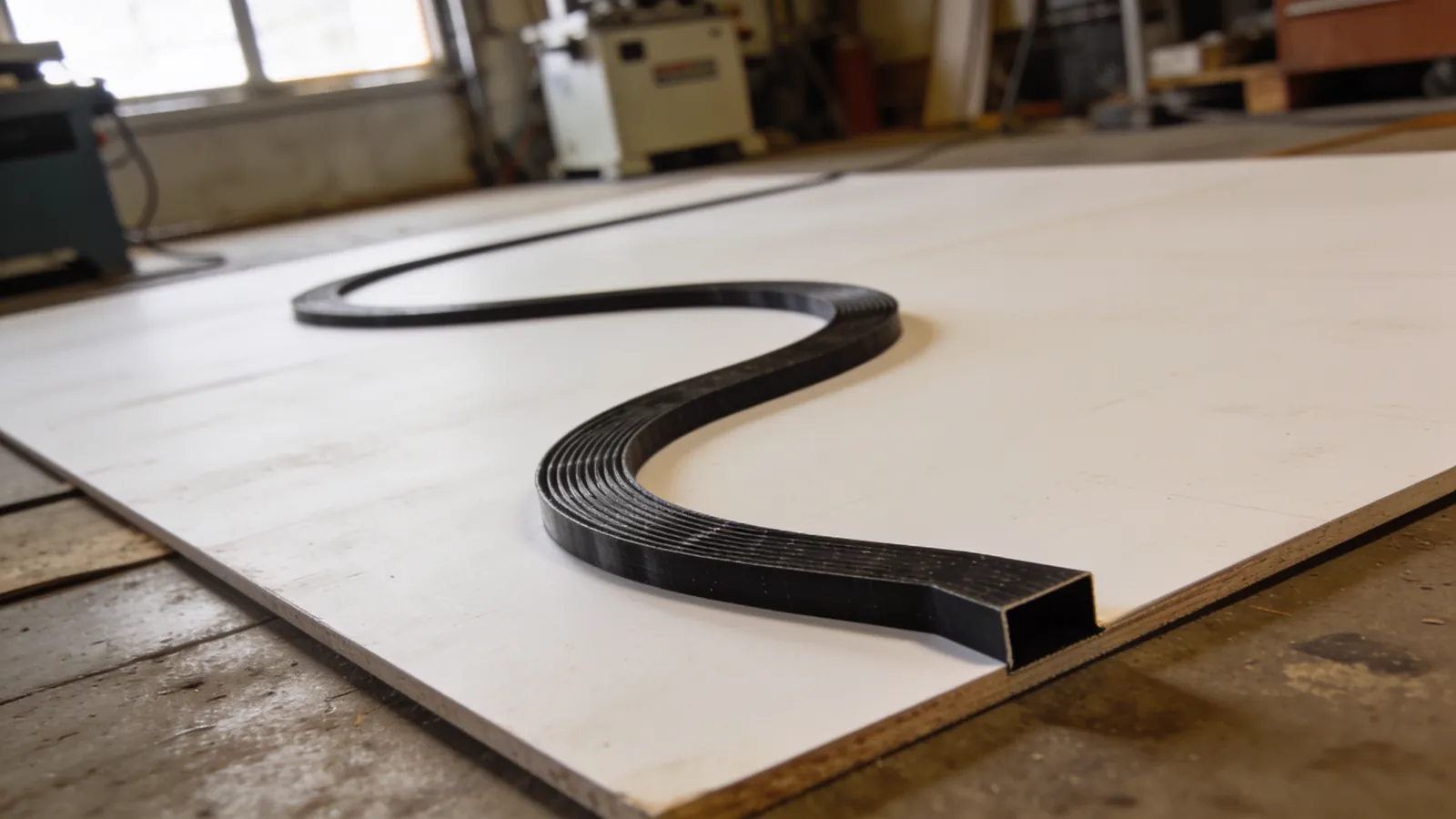
- Surface: White, matte MDF board or large white cardboard. A glossy surface causes reflections and confuses the sensor.
- Line: 19 mm black electrical tape or matte black electrical tape. Do not use shiny tape.
- Dimensions: At least 150 × 100 cm. You won’t be able to observe realistic cornering behavior on a smaller track.
What to Put on the Track
Don’t just draw a simple oval and call it “good.” The test track must include the following:
- Long straight section: To test maximum speed.
- Wide turn: Stability at high speeds.
- Sharp 90-degree turn: To test the width of the sensor array.
- S-curve: To see how quickly the robot can change direction.
- Intersection: A test of the robot’s exception handling code.
- Short gap (2–3 cm): Line-loss recovery behavior.
Measurable test
“It’s better now” is not a sufficient evaluation. Time the lap with a stopwatch and record every adjustment in a notebook:
| Test | Kp | Kd | Base speed | Lap Time | Result |
|---|---|---|---|---|---|
| 1 | 0.08 | 1.2 | 140 | 18.4 s | Stable |
| 2 | 0.08 | 1.2 | 170 | 15.1 s | He lost control on a sharp turn |
| 3 | 0.08 | 2.0 | 170 | 15.3 s | Stable |
| 4 | 0.10 | 2.0 | 190 | 13.8 s | Slight oscillation |
This table contains the log of a three-hour tuning session. Without it, you’ll have to repeat the same tests.
Special cases
Line loss
The robot must know what to do if it completely loses the line. The most reliable method is to continue turning in the direction of the last known error:
if (toplamDeger < 50) {          // hiçbir sensör çizgi görmüyor
  if (sonHata > 0) motorSur(MAKS_HIZ, -MAKS_HIZ);   // sağa ara
  else             motorSur(-MAKS_HIZ, MAKS_HIZ);   // sola ara
  return;
}
Intersections and 90-degree turns
If there is an intersection on the track, all sensors will detect black at the same time. Handle this as a separate condition; otherwise, the weighted average will produce a meaningless center value:
bool kesisimMi() {
  int siyahSayisi = 0;
  for (int i = 0; i < SENSOR_SAYISI; i++) {
    if (normalize(analogRead(sensorPin[i]), i) > 700) siyahSayisi++;
  }
  return siyahSayisi >= SENSOR_SAYISI - 1;
}
Common Mistakes
- Failing to calibrate. The most common and most costly mistake.
- Changes in sensor height. A flexing chassis produces noise that you cannot resolve in the code.
- Setting the “Ki” coefficient too high. The robot will begin to oscillate around the line with increasing amplitude.
- Failing to account for the motor driver. When you set PWM to 255, make sure the motor is actually receiving full power.
- Testing only on a straight track. Test the robot on a track that includes sharp turns, intersections, and gaps.
Next Step
Once your line-following robot is complete, you’ll have more than just a robot—you’ll have gained practice in building a control system. The same PID logic works exactly the same way in steering control for autonomous vehicles, in balancing robots, and in motor speed control.
If you want to strengthen your fundamentals on the Arduino side, the Arduino Beginner’s Guide is a good place to start; if you’re thinking about upgrading your board, the “ESP32 or Arduino?” article is a great next step.
Frequently asked questions
Çizgi izleyen robotta kaç sensör kullanmalıyım?
Başlangıç için 5 sensör yeterlidir ve öğrenmesi kolaydır. Yarışma hızına çıkmak istiyorsanız 8–12 sensörlü dizi kullanın: daha fazla sensör, çizginin konumunu daha hassas ölçmenizi ve dolayısıyla daha yüksek hızda kararlı kalmanızı sağlar.
Çizgi izleyen robot neden virajda çizgiden çıkıyor?
Üç tipik sebep var: hız virajın yarıçapına göre çok yüksek, türev (D) katsayısı düşük olduğu için robot geç tepki veriyor, ya da sensör dizisi tekerlek ekseninden çok uzakta. Önce hızı düşürüp kararlılığı doğrulayın, sonra D katsayısını artırın.
PID katsayılarını nasıl ayarlarım?
Sırayla ilerleyin: önce Ki ve Kd sıfırken Kp’yi robot çizgiyi takip edip hafifçe salınana kadar artırın. Sonra Kd’yi bu salınım sönene kadar yükseltin. Ki’yi en son ve çok küçük değerlerle ekleyin; çizgi izleyende çoğu zaman Ki=0 en iyi sonucu verir.
Kızılötesi sensör mü kamera mı kullanmalıyım?
Klasik çizgi izleyen yarışmaları için kızılötesi yansımalı sensör dizisi doğru tercihtir: milisaniyenin altında yanıt verir ve işlemci yükü yok denecek kadar azdır. Kamera, çizgi dışında nesne veya işaret tanıma gerektiren otonom görevler için anlamlıdır.
Ortam ışığı sensörleri etkiliyor, ne yapmalıyım?
Sensör dizisini bir siperlikle gölgeleyin, zeminden yüksekliği 3–5 mm’de sabitleyin ve her yarışmadan önce mutlaka o pistin üzerinde kalibrasyon yapın. Sabit eşik değeri yerine kalibrasyonla bulunan min/max değerlere göre normalizasyon kullanın.
Comments
0No comments yet. Be the first to comment!